Demystifying Camera Pipeline in Embedded Vision Systems
Wide variety of industries from surveillance to robotics uses cameras to perceive the world. Choosing the correct implementation of the camera pipeline can make or break the embedded vision application's performance. This article puts light on various aspects of the camera pipeline.
Photosite
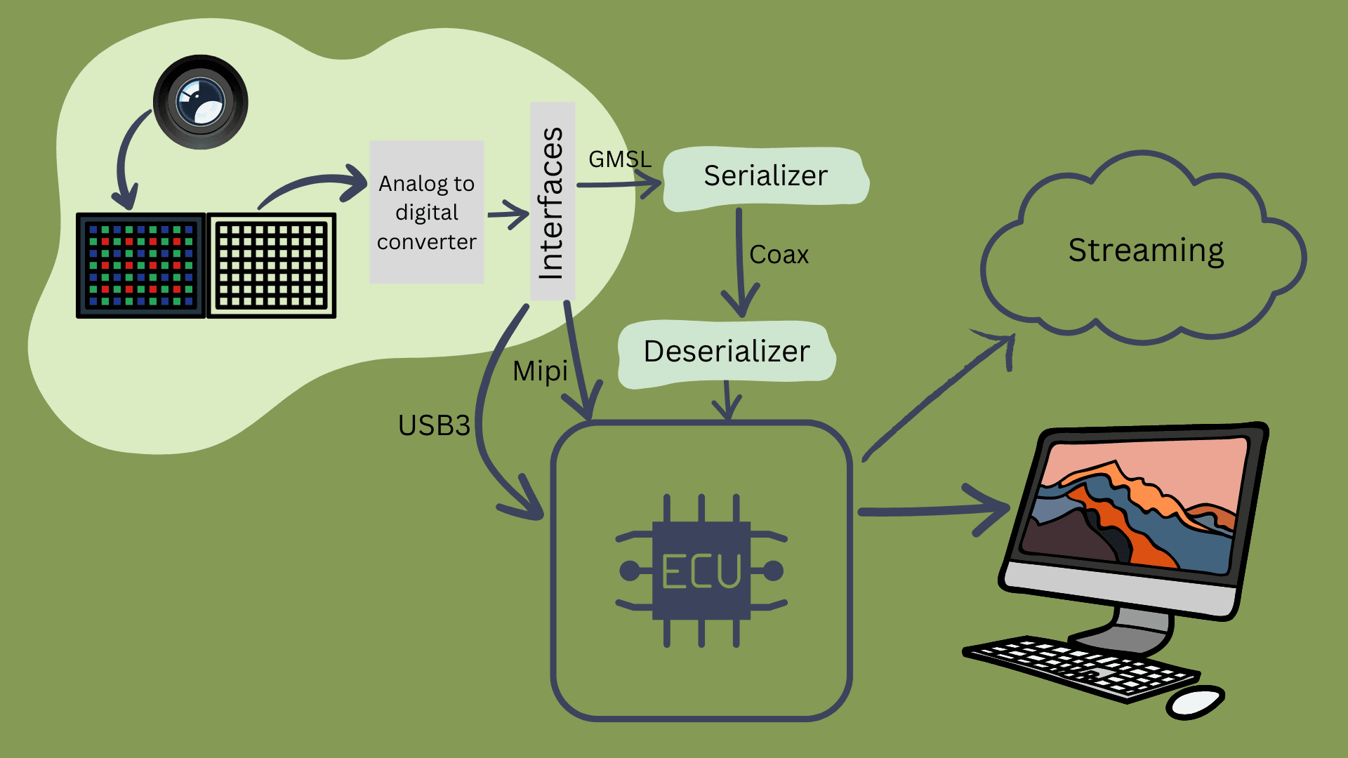
Everything starts with the lens capturing light from the target scene. Lens mounted onto the camera accumulates the light on focus on to the imager. Imager is a sensor that is sensitive to visible light. The area of sensor is covered with millions of microscopic objects called photosites that are arranged in a rectangular grid. These photosites produce an electrical charge directly proportional to the amount of light if receives. If we consider a camera capable of recording at Full HD, it has approximately 1920x1080 (2M) photosites. Each photosite is responsible for each pixel in the image. These photosites are sensitive to the light but not sensitive to the color. Hence it cannot capture the color. To get a color image, a thin filter is placed over the photosites. This layer is referred to as Color Filter Array (CFA) or Bayer filter in regular usage.
Demosaicing/Debayering
This filter consists of a Mosaic of RGB blocks with each of them placed on the photosite. Every pixel records only one color either red, blue or green. In this pattern there will be twice as many green pixels compared to the blue and red ones as human vision is more sensitive to green. This pattern is referred to as Bayer pattern. At each pixel the two missing channels are calculated by interpolating the neighboring pixels. This process is referred to as Debayering or Demosaicing. Most modern cameras apply a non linearity factor called gamma to these images. Human vision is non linear. When the scene is started with dimmed light source and the slowly the intensity of the scene double, the perceived change in intensity will not be double. This behavior is often replicated in cameras using the gamma factor. Also most modern cameras allow to capture linear image i.e. the image without gamma factor. This is often called RAW format. RAW images also contain more than 8 bits per channels allowing to possibility of reading more colors.
Interfaces
All the information being read should be available to process in the application layer either in a stored format or live streaming format. Each image being read from the imager contributes to huge amount of data. For example for a Full HD image, for each image, there will be around 2M pixels. Each pixel consists of 3 color channels contributing to over 6M data elements. If 8 bits are used store each data element, approximately 50 Mb/s of information is used to store each image. And running the imager at 60 frames/sec can lead to a data rate of around 3.5GBps. Interfaces help in managing this humongous data rates. Some of the popular ones are MIPI CSI-2, GMSL, USB 3.0 and GigE.
MIPI CSI-2
This interface was developed with mobile devices in consideration. MIPI CSI-2 interface has around 4 lanes each capable of transferring up to 2.5 Gbps contributing to a maximum bandwidth of 10 Gbps. This interface is much faster and very reliable for handling videos from 1080p to 8k and beyond. It also uses fewer resources from the CPU. The drawback is it relies on extra drivers to work and the maximum length of the cable is under 30 cm.
USB interface
Well known for its plug and play capabilities, USB makes development easy compared to other interfaces. USB 3.0 has a maximum bandwidth of 480 Mbps. This interface cannot run high resolution cameras at high speed. This uses cable up to 5 meters in length. Any cable longer than that uses boosters.
GMSL
GMSL is mainly targeted at the automotive space. It is a multigigabit ethernet point to point connection. It can carry both power and video data over a single coaxial cable up to lengths of 15m. SerDes is the technique that enables this transmission. It can transfer a video at a speed of up to 6 GB/s
GigE
This ethernet interface, can transfer data rate up to 120 MB/s with a maximum cable length of up to 100m. It supports multi camera functionality. It can be seamlessly integrated into various embedded vision applications as it is in the sweet spot of bandwidth, cable length and multi-camera support.
Any embedded camera supports most of these interfaces. These interfaces play a huge role in the performance that can be squeezed out of the application.
Data Transfer
Raw data is a lot to transfer around and different applications different ways to handle this data transfer either within the same system or from system to system.
One of the ways is data compression. Especially when working with video/image data, using data compression can save a lot of bandwidth in terms of transfer and also save a lot of storage when the video/image needs to be saved. Data compression can be an blog in its own.
Since this blogs highlights on Embedded vision, two most popular video compression techniques used in video compression are H264 and H265 encoding/decoding. One famous image compression method is JPEG compression. All the compression techniques mentioned here are lossy compression. These exploit the fact that the human visual system is less sensitive to fine detail in the image compared to broader features.
Glass to glass Latency metric
Every system design needs a good evaluation system. Since embedded vision systems usually are latency critical systems depending on the application the system needs a good metric to evaluate the credibility of the system. one of the metric used is Glass to glass Latency.
Glass to glass latency is defined as the time delay between when light hits a camera sensor and when the resulting image appears on a viewer's screen. One really good way to measure this is to centralize the emitting of a led light source on a camera lens and its detection on a computer screen. This method doesn't require time synchronization and increases the precision. Glass to glass here is measured as a time delta between when light is activated and when it is detected.
References
- Bachhuber, C., & Steinbach, E. (2016, September). A system for high precision glass-to-glass delay measurements in video communication. In 2016 IEEE international conference on image processing (ICIP) (pp. 2132-2136). IEEE.